The purpose of this Learning Unit is to enable a mason to read and interpret simple construction drawings and sketches for housing projects and to mark out houses.
By the end of this Learning Unit the mason should be able to:
Read and interpret construction drawings and sketches for houses including toilet installations,
Set out foundations, walls, and sewer tanks,
Transfer and maintain levels when carrying out masonry works.
houses have diverse designs, and it is therefore important that mason can read and interpret simple construction drawings and sketches. All construction details are usually specified in drawings. For this reason, it is essential to be able to read and understand them and thereby adhere to the designs when building the house. The general ground plan describes the position and dimensions of the house. Other more detailed drawings explain the location and levels of the foundation and all other dimensions of the house. This information is required to be able to set out every step of works, starting with clearing and levelling the ground, followed by excavating the foundation, building the foundation and so on until the house is complete. Every work step requires setting out and checking the measurements and levels. This Learning Unit provides the necessary information on how to read and interpret drawings, how to set out for works and how to transfer and check levels.
Reading and interpreting construction drawings
This section describes how to:
Read and interpret basic work drawings, sketches and basic specifications,
Identify and interpret abbreviations and symbols on plans and work drawings;
Identify any preliminary work from plans, and drawings; and
Use plans, drawings and specifications to determine the quality and types of materials required.
Summary
Construction drawings for houses consist of:
(i) Plans; showing all walls and openings as seen from top (bird’s eye view) with dimensions;
(ii) Sections; showing levels, dimensions and construction details in a vertical view (as if cut through with a knife). To show the important details of a structure, several sections may be required;
(iii) Elevations: showing the outside (face) of the building.
Reading and interpreting basic working drawings and sketches
The purpose of drawings is to present clear, concise and easily readable information on a proposed building project. This way everyone involved in the project is informed of what exactly is required. Various types of drawing methods are used to communicate this information. Construction drawings are used to communicate ideas and information in a graphic form. Sketches are prepared first, then final working drawings are completed once the design details have been decided. Each drawing should be neat and clearly labelled. Sketches are not always drawn to scale. The exact location, dimensions and levels are shown on the construction drawings. These usually include a plan and cross-sections. The drawings or sketches include all essential structures, e.g. walls, windows, doors and columns. It also shows the exact measurements of these elements and describes the materials to be used. Unlike sketches, building drawings are presented at a specific scale. When preparing a set of work drawings it is not possible to draw the building elements at full size. Therefore the drawings are reduced proportionally to a size allowing it to fit on conveniently sized drawing paper. This reduction process is called scaling. The extent to which the drawings have been reduced from their real size is clearly marked on the drawing. For example, a scale of 1:100 means 1cm on the drawing represents 100cm of the object in real terms. All dimensions should be precisely indicated on the drawing irrespective of the scale. In house construction the most common units of measure are metres, centimetres or millimetres. Dimensions on drawings are usually only meant to be read, not measured. The plan is the view seen when looking directly down from above. It provides information about:
Overall length and width;
Dimensions of parts of the construction;
Position and size of windows and doors;
Function of areas such as kitchen, toilet, etc.;
Scale of the plan.
It is often necessary to show the details of a building that are normally hidden. To do this it is necessary to imagine that it has been sliced through or sectioned. The position of a section is indicated on the plan using a section line. A section view differs from an elevation, as it shows the details through the construction. It can provide information about:
Foundation shape and sizes and positioning of reinforcement steel;
Floor and ground levels;
Roof design;
Window and door heights.
An elevation is the view from one side of the construction when looking at it from outside. It can provide information about:
Shape of the building from each direction;
Height of the construction;
Positions of doors and windows;
Window details and height;
Roof shape.
Setting out
This section explains how a rural mason can set out the works as per sketches and drawings. Setting out is bringing the dimensions from a plan to the real situation. The activity consists of establishing the exact location and measurements of the house to be built.
Setting out the building perimeter
The first activity of setting out is to clear the ground of any debris, vegetation and other obstructions. Ideally the ground should be level, although in hilly areas houses can also be constructed on slopes. Before starting construction works it is necessary to know the exactly location and size of the house. Therefore, the exact position of the corners of the house is defined and marked on the ground. This is usually done by fixing reference points outside the actual perimeter of the building From these reference points it is always possible to re-measure and check the exact position of the foundation and walls. According to the measurements on the construction plan the building is set out with stone or brick pedestals that indicate the exact position of the centrelines of the walls.
Work method:
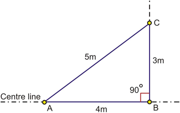
Ensuring right angles (90 degrees) is important when setting out the initial perimeter of the house. This can easily be achieved using the 3:4:5 triangle method. A triangle, which has sides of length 3 metres, 4 metres and 5 metres, will always have a right angle between the 3-metre side and the 4-metre side. One can therefore construct a right angle using only a tape measure as follows:
- Measure the length A to B of 4 metres along the line from where a perpendicular line needs to be defined. Place pegs exactly at points A and B,
- Hold the zero point of the tape measure on the peg A,
- A second person holds the mark 8.0 metres on the tape measure on peg B,
- A third person holds the tape measure on mark 5.0 metres, which will lead to point C when the tape measure is pulled tight. Set a peg on point C.
- Extend the now perpendicular line from point B to point C to any length as required
Labour:
- Rural mason
- Laborers to assist
Tools:
- Tape measure
- Hammer
Material:
- String
- Pegs
Quality checkpoints:
- After constructing the right angle check again that the triangle lengths represent exactly the 3:4:5 proportions.
- Ensure that all reference pegs are firmly fixed.
Work method:
- Clear the ground where the house will be located and ensure that it is level.
- Place solid pedestals on all corners, approximately 1.5 m away from the planned outside walls of the building.
- Ideally all pedestals should be of the same height and keep the string well off the ground.
- Mark the centre of the outer walls using a string line and tape measure. Fix the string tightly so it does not sag.
- The string lines should cross each other at a right angle. Use the 3:4:5 string method to obtain the 90 degree angles for the house corners
- Check the diagonals. For a perfect layout they must be of equal length..
Labour:
- Rural mason
- Laborers to assist
Tools:
- Tape measure
- Plumb bob
Material:
- Bricks, blocks or stone for pedestals
- Cement mortar for pedestals
- Strong string
Quality checkpoints:
- Make sure the pedestals are solid enough so they do not easily shift.
- Check that the measured dimensions on the ground conform with the drawings.
- Check that all corners have a right angle and that the two diagonals are or equal length.
tenetur reprehenderit voluptatem qui aut. consequuntur ullam consequatur rerum distinctio quod laboriosam saepe et aspernatur ipsum voluptatem vero repellat quia. reprehenderit explicabo exercitatione