A gravity dam is a solid concrete or masonry structure which ensures stability against all applied loads by its weight alone without depending on arch or beam action. Such dams are usually straight in plan and approximately triangular in cross-section. Gravity dams are usually classified with reference to their structural height which is the difference in elevation between the top of the dam (i.e., the crown of the roadway, or the level of the walkway if there is no roadway) and the lowest point in the excavated foundation area, exclusive of such features as narrow fault zones (1). Gravity dams up to 100 ft (30.48 m) in height are generally considered as low dams. Dams of height between 100 ft (30.48 m) and 300 ft (91.44m) are designated as medium-height dams. Dams higher than 300 ft (91.44 m) are considered as high dams.
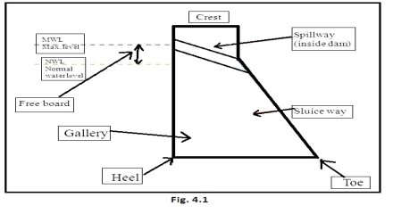
The downstream face of a gravity dam usually has a uniform slope which, if extended, would intersect the vertical upstream face at or near the maximum water level in the reservoir. The upper portion of the dam is made thick enough to accommodate the roadway or other required access as well as to resist the shock of floating objects in the reservoir. The upstream face of a gravity dam is usually kept vertical so that most of its weight is concentrated near the upstream face to resist effectively the tensile stresses due to the reservoir water loading. The thickness of the dam provides resistance to sliding and may, therefore, dictate the slope of the downstream face which is usually in the range of 0.7 to 0.8 (H) : 1(V). The thickness in the lower part of the dam may also be increased by an upstream batter. When it is not feasible to locate the spillway in the abutment, it may be located on a portion of the dam in which case the section of the dam is modified at the top to accommodate the crest of the spillway and at the toe to accommodate the energy dissipation. The stability requirements of such overflow sections of gravity dams would be different from those of non overflow gravity dams.
FORCES ON A GRAVITY DAM
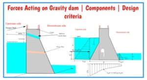
The forces commonly included in the design of a gravity dam . These are as follows (2, 3, 4):
(i) Dead Load
The dead load (Wc) includes the weight of concrete and the weight of appurtenances such as piers, gates, and bridges. All the dead load is assumed to be transmitted vertically to the foundation without transfer by shear between adjacent blocks.
(ii) Reservoir and Tail-water Loads (Ww , Ww′, W1, and W1′)
These are obtained from tail-water curves and range of water surface elevations in reservoir obtained from reservoir operation studies. These studies are based on operating and hydrologic data such as reservoir capacity, storage allocations, stream flow records, flood hydro graphs, and reservoir releases for all purposes. In case of low overflow dams, the dynamic effect of the velocity of approach may be significant and should, therefore, be considered. If gates or other control features are used on the crest, they are treated as part of the dam so far as the application of water pressure is concerned. In case of non-overflow gravity dams, the tail-water should be adjusted for any retrogression. Any increase in tail-water pressure due to curvature of flow in the downstream bucket of an overflow type gravity dam should also be considered in the design of gravity dams (4).
(iii) Uplift Forces
Uplift forces (U) occur due to internal hydraulic pressures in pores, cracks, and seams within the body of a dam, at the contact between the dam and its foundation, and within the foundation. The distribution of internal hydrostatic pressure along a horizontal section through a gravity dam is assumed to vary linearly from full reservoir pressure at the upstream face to zero or tail-water pressure at the downstream face, and to act over the entire area of the section. The pressure distribution is also adjusted depending upon the size, location, and spacing of internal drains. Experimental and analytical studies indicate that the drains set in from the upstream face at 5 per cent of the maximum reservoir depth and spaced laterally twice that distance will reduce the average pressure at the drains to approximately tail-water pressure plus one-third the difference between reservoir water and tail-water pressures It is assumed that uplift forces are not affected by earthquakes (2).
(iv) Silt Load
The construction of a dam across a river carrying sediment invariably results in reservoir sedimentation which causes an additional force (Ws) on the upstream face of the dam. The horizontal silt pressure is assumed equivalent to a hydrostatic load exerted by a fluid with a mass density of 1360 kg/m3. The vertical silt pressure is assumed equivalent to that exerted by a soil with a wet density of 1925 kg/m3.
(v) Ice Pressure
If the designer anticipates the formation of an ice sheet of appreciable thickness and its remaining on the reservoir water surface for a long duration, the ice pressures must be computed using a suitable method of their estimation. In the absence of such a method, ice pressure may be taken as 250 kPa (250 kN/m2) applied over the anticipated area of contact of ice with the face of the dam (2).
(vi) Wave Pressure
The upper portion of a dam is also subjected to the impact of waves. Wave pressure against massive dams of large height is usually of little importance. Wave pressure is related to wave height hw as follows (2):
(a) The maximum wave pressure pw (in kilopascals) occurs at 0.125 hw above the still water level and is given by the equation
pw = 24 hw
where, hw is the height of the wave in metres.
(b) The total wave force Pw (in kilonewtons) is given by
Pw = 20 hw
and acts at 0.375 hw above the still water level in the downstream direction.
(c) The wave height hw can be calculated using the following relations:
hw = 0.032 VF + 0.76 – 0.27 F1/4 for F < 32 km
hw = 0.032 VF for F > 32 km
Here, V is the wind velocity in kilometres per hour and F is the fetch in kilometres. The height of the wave and the wind set-up decide the freeboard which is the vertical distance between the top of the dam and the still water level. The wind set-up S (in metres) is estimated by the Zuider Zee formula
S = V2F / 62000 D
in which, D is the average depth in metres over the fetch distance F.The minimum freeboard should be equal to wind set-up plus 4/3 times wave height above the normal pool elevation or above maximum reservoir level corresponding to the design flood, whichever gives higher crest elevation for the dam (2). The freeboard shall not, however, be less than 1.0 m above the mean water level corresponding to the design flood.
(vii) Earthquake
Gravity dams are elastic structures which may be excited to resonate by seismic disturbances. Such dams should be designed so that they remain elastic when subjected to the design earthquake. The design earthquake should be determined considering (i) historical records of earthquakes to obtain frequency of occurrence versus magnitude, (ii) useful life of the dam, and (iii) statistical approach to determine probable occurrence of earthquakes of various magnitudes during the life of the dam. A gravity dam should also be designed to withstand the maximum credible earthquake which is defined as the one having a magnitude usually larger than any historical recorded earthquake (3).Earthquakes impart random oscillations to the dam which increase the water and silt pressures acting on the dam and also the stresses within the dam. An earthquake movement may take place in any direction. Both horizontal and vertical earthquake loads should be applied in the direction which produces the most unfavourable conditions. For a gravity dam, when the reservoir is full, the most unfavourable direction of earthquake movement is upstream (so that the inertial forces acting downstream may result in resultant force intersecting the base of the dam outside middle-third of the base besides increasing the water load and, therefore, the increased overturning moment) and is downward for vertical earthquake movement as it causes the concrete, and water above the sloping faces of the dam to weigh less resulting in reduced stability of the dam. When the reservoir is empty, more unfavourable is the downstream ground motion causing inertial forces to act upstream so that the resultant may intersect the base of the dam outside middle-third of the base. The effect of earthquake forces depends on (i)their magnitude which, in turn, depends on the severity of the earthquake, (ii) the mass of the structure and its elasticity, and (iii) the earthquake effects on the water load. For estimation of earthquake load, knowledge of earthquake acceleration or intensity, usually expressed in relation to acceleration due to gravity g, is useful. This ratio of earthquake acceleration to gravitational acceleration is termed seismic coefficient and is designated as αh. The value of seismic coefficient for horizontal as well as vertical earthquake accelerations for different zones of the country are different and can be obtained from the Codes.
CAUSES OF FAILURE OF A GRAVITY DAM
A gravity dam may fail on account of overturning. For a gravity dam to be safe against overturning, the dimensions of the dam should be such that the resultant of all the forces intersects the base of the dam within its middle-third portion. Consider any horizontal section (including the base) of a gravity dam and the resultant of all the forces acting on the dam above the section. If the line of action of this resultant pass outside the downstream edge of the section, the dam would overturn. However, the section of a gravity dam is such that the line of action of the resultant force is within the upstream and downstream edges of the section and overturning would never results. But, if the line of action of the resultant passes sufficiently outside the middle-third of the horizontal section, it may cause crushing of the downstream edge of the section. This would reduce the effective width and, hence, the sliding resistance of the section and may cause the resultant to pass outside the dam section. Further, when the resultant passes downstream of the middle-third of the horizontal section, it induces tensile stresses at the upstream edge of the section. These tensile stresses may cause cracks in the dam section which would result in increased uplift pressure. The stabilising forces would, thus, be reduced. It follows, therefore, that before a gravity dam overturns bodily, other types of failures, such as crushing of toe material, sliding, cracking of the material due to tension, and increase in uplift may occur. A gravity dam is considered safe against overturning if the criteria of: (i) no tension on the upstream face, (ii) adequate resistance against sliding, and (iii) suitable quality and sufficient strength of concrete/masonry of dam and its foundation are satisfied.