Embankment dams are water impounding structures composed of natural frag mental materials (such as soil and rock) and consist of discrete particles which maintain their individual identities and have spaces between them. These materials derive strength from their position, internal friction, and mutual attraction of their particles. Unlike cemented materials, these frag mental materials form a relatively flexible structure which can deform slightly to conform to the foundation deflection without causing failure.
Embankment dams have been in existence for many centuries. The earliest forms of these dams were made naturally by landslides and rockfalls which cut off streams and formed natural dams. A 300-m natural dam of this type was created by a landslide which occurred in 1840 on the upper reaches of the Indus river (1). This dam, however, burst just after six months of its formation resulting in great loss of life and property in the valley. Man-made tanks (or reservoirs) constructed in the early days of civilisation are found in the southern part of India and Sri Lanka.
These tanks have been constructed by building earthen embankments. One such earthen embankment 17.6 km long, 21.34 m high, and containing about 13 million cubic metres of earth material was completed in 504 BC (2). Till around 1925, the methods of design of an embankment dam were based on thumb rules and the heights of such dams rarely exceeded 30 m.
The recent developments in soil mechanics have, however, made it possible to design an embankment dam with more confidence. This has resulted in much higher embankment dams such as Beas (116 m) and Ramganga (125 m) dams of India, Goschenenalp dam (156 m) in Switzerland, Oroville dam (224 m) in the USA, Mica Greek dam (235 m) in Canada, and Nurek dam (300 m) in the erstwhile USSR. Conditions favouring the selection of an embankment dam are as follows (3):
(i) Significant thickness of soil deposits overlying bedrock,
(ii) Weak or soft bedrock which would not be able to resist high stresses from a concrete dam,
(iii) Abutments of either deep soil deposits or weak rock,
(iv) Availability of a suitable location for a spillway, and
(v) Availability of sufficient and suitable soils from required excavation or nearby borrow areas.
Embankment dams are mainly of two types:
(i) Earth-fill or earth dams, and
(ii) Rock-fill or earth-rock dams.
The bulk of the mass in an earth-fill dam consists of soil, while in the rock-fill dam it consists of rock material. The design principles for the two types of embankment dams are similar. Earth dams are further divided into the following types:
(i) Homogeneous earth dam, and
(ii) Zoned earth dam.
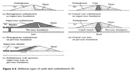
Homogeneous earth dams are constructed entirely or almost entirely of one type of earth material. A zoned earth dam, however, contains materials of different kinds in different parts of the embankment. A homogeneous earth dam is usually built when only one type of material is economically available and/or the height of the dam is not very large.
A homogeneous earth dam of height exceeding about 6 to 8 m should always have some type of drain constructed of material more pervious than the embankment soil (4). Such drains reduce pore pressures in the downstream portion of the dam and thus increase the stability of the downstream slope. Besides, the drains control the outgoing seepage water in such a manner that it does not carry away embankment soil, i.e., ‘‘piping’’ does not develop.
Such a dam is also categorised as homogeneous (sometimes ‘modified homogeneous’) dam. Some of the benefits of a zoned earth dam can be achieved in a homogeneous earth dam by either selective placement of soil or using different construction methods in different parts of the embankment and thus creating zones of different characteristics.
The most common type of an earth dam usually adopted is the zoned earth dam as it leads to an economic and more stable design of the dam. In a zoned earth dam, there is a central impervious core which is flanked by zones of more pervious material. The pervious zones, also known as shells, enclose, support, and protect the impervious core.
The upstream shell provides stability against rapid drawdowns of reservoir while the downstream shell acts as a drain to control the line of seepage and provides stability to the dam during its construction and operation. The central core provides imperiousness to the embankment and reduces the seepage. The maximum width of the impervious core will be governed by stability and seepage criteria and also by the availability of the material.
An earth dam with a sufficiently thick impervious core of strong material with pervious outer shells can have relatively steeper embankment slopes limited only by the foundation and embankment characteristics. However, a thin core dam is usually more economical and more easily constructed because of lesser amount of fine-grained soil to be handled. Core widths of 30 to 50% of the water head are usually adequate for any type of soil and any dam height while core widths of 15 to 20% of water head are thin and considered satisfactory, if adequately designed and constructed filter layers are provided . Core widths of less than 10% of water head should not be used as far as possible.
The impervious core can be placed either as a vertical core or as an upstream sloping core, each of which has some advantages over the other. A vertical core results in higher pressure on the contact between the core and foundation which, in turn, reduces the possibility of leakage along the contact. Besides, for a given quantity of impervious material, the vertical core will have greater thickness. The main advantage of upstream sloping core is that the main downstream shell can be constructed first and the core placed later – an advantageous feature in areas which have short periods of dry weather suitable for building a core of fine-grained soil.
Besides, foundation grouting can be carried out while the downstream embankment is being constructed. A rock-fill dam is an embankment which uses large-sized rock pieces to provide stability and an impervious membrane to provide water tightness. Materials used for the membrane are earth, concrete, steel, asphalt, and wood. The impervious membrane can be placed either on the upstream face of the dam or as a core inside the embankment. The upstream face of the dam is, however, more suitable for placing the impervious membrane due to the following reasons:
(i) The upstream impervious membrane, with a suitable drain behind it, prevents seepage from entering the embankment. This reduces pore pressures and prevents the embankment mass from being submerged. Both these effects result in greater stability of the embankment.
(ii) The upstream impervious membrane is accessible for inspection and repair.
(iii) The upstream impervious membrane also serves a secondary function of wave protection.
(iv) The upstream impervious membrane can be built after completion of the embankment.
This would permit initial settlement of the embankment without affecting the membrane adversely.
DESIGN CONSIDERATIONS
The design of an embankment dam is based on analytical considerations as well as on experience.
The main steps in the design of an embankment dam are as follows:
(i) A thorough exploration of the foundation and abutments.
(ii) Evaluation of the quantities and characteristics of all the embankment construction materials available within a reasonable distance of the dam site.
(iii) A study of all the factors which may influence the design.
(iv) The selection of trial designs.
(v) Analysis of the safety of the trial designs.
(vi) The modification of the designs to satisfy the minimum stability requirements.
(vii) The preparation of detailed cost estimates.
(viii) The final selection of the design which seems to offer the best combination of economy, safety, and convenience in construction.
Factors Influencing the Design of an Embankment Dam
(i) Materials Available for Construction – One of the main advantages of an embankment dam is the availability of construction material free of charge at or near the dam site. Depending upon the type of material available, the designed embankment may either be a homogeneous earth dam (when the soil available is impervious), a zoned earth dam (when both pervious and impervious soils are available) or a rock-fill dam (if rock is available and impervious material is not). The design may also incorporate use of materials from required excavation (for spillway construction) for reasons of economy.
(ii) Foundation Characteristics – An embankment dam can be constructed on almost any kind of foundation. Foundation characteristics mainly affect the foundation treatment which, in some cases, may be the most difficult and important part of the design and construction of an embankment dam. Besides, the embankment dimensions would be considerably influenced. For example, a softer foundation would necessitate an embankment with flatter slopes, broader cross-section, a larger free board (to mitigate the effects of embankment settlement), considerations for differential settlement cracks, and measures for control of under seepage to avoid the danger of piping.
(iii) Climate – It is generally difficult to handle fine-grained soils during the rainy season and control the construction moisture content of the fine-grained soils in arid regions. As such, if the construction of the embankment has to be carried out during the rainy season, it is advisable to have sloping core embankment. Similarly, in arid regions, one extra year may be required for constructing a small reservoir for storing flood runoff for the purpose of construction of the dam.
(iv) Shape and Size of Valleys – A dam site with broad valleys and gently sloping abutments may not affect the design of an embankment. However, narrow valleys and steep abutments may necessitate special design provisions. For example, because of the limited working space in a narrow valley, a simpler design requiring few special construction provisions is preferable. If the construction and maintenance of haul roads on the abutments at different elevations become difficult and costly, one may have to design a rock-fill embankment which can be constructed by dumping rock in high lifts from relatively few haul roads.
(v) River Diversion – If a river diversion scheme is to be implemented by the construction engineer or the contractor, it increases the problem of the designer who must envisage all possible ways of river diversion and make his design adaptable to each of these ways. On major rivers, however, it may be advisable to specify the river diversion scheme and design the embankment accordingly. In a narrow valley, the river is diverted through a tunnel or conduit. In wider valleys, parts of the embankment on the two abutments are constructed while letting the river flow through the central region of the valley. This central part of the embankment is constructed only at the end and is known as the ‘closure’ section. The construction of the closure section is carried out rapidly to prevent over topping of the dam and, hence, special design details (viz., providing extra filter drains, different designs for different embankment sections in order to use the material available on the two abutments, and so on) and construction details (such as compacting the closure section at higher water content, keeping a reserve of borrow material to achieve a rapid construction rate for closure, etc.) are specified. If coffer dams of large volumes are used for diversion purposes, it would be economical to incorporate these into the dam embankment, if possible.
(vi) Probable Wave Action – The severity of the wave action and the amount of protection needed for the upstream face of the embankment mainly depends on the wind velocity and the length of the reservoir. The waves drive repeatedly against the embankment and, thus, cause the embankment erosion. A layer of dumped rock rip rap is considered the most effective and economical wave protection.
(vii) Time Available for Construction – The design of an embankment is dependent on the time available for construction. A shorter construction period, in case of high dams, may result in higher pore pressures requiring relatively flatter slopes. When construction time is limited, it may not be possible to use the material from the required excavation, or it may be that only a part of it can be used. Similarly, under seepage measures would also be affected by the time available for construction. Handling of fine-grained soils requires considerable time and, therefore, it may be desirable to provide a manufactured impervious membrane to save time.
(viii) Function of the Reservoir – The function of the reservoir determines the allowable water loss due to seepage through the embankment and foundation. Accordingly, the embankment section may be relatively more impervious (for conservation reservoirs) or relatively more pervious (for flood control reservoirs).In hydroelectric projects, the upstream face of the dam will be subjected to a ‘‘sudden draw down ‘condition which may necessitate the provision of a flatter upstream slope.
(ix) Earthquake Activity – In regions of seismic activity, the designer may have to adopt more conservative design features such as better filters, downstream drains of larger capacity, thicker cores of more piping resistant materials, flatter side slopes, longer construction time, and so on.